Bridge Rectifier Circuit
 |  |  | ||
| ||||
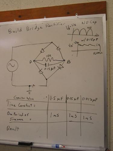
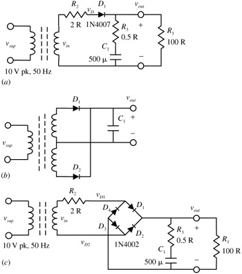
Notes and details for the bridge rectifier circuit using four diodes used as a full wave rectifier circuit especially in power supplies. Here is the circuit diagram, working and output wave forms of a full wave bridge rectifier.A rectifier is an AC to DC voltage converter circuit. A full wave rectifier circuit rectifies the AC in both directions providing a DC signal for each AC cycle. Bridge Rectifier Circuit schematic using 4 diodes labeled The maximum DC voltage you could expect to obtain from a transformer with an 18V rms secondary using a bridge rectifier circuit with a filter capacitor is about 24V. A full-wave bridge rectifier circuit with a 1K ohm load operates from a 120V (rms) 60Hz household supply though a 10-to-1 step-down transformer having a single Bridge Rectifier Circuit Problem: BarryMinnesota13: 2/4/13 8:15 PM: Given the following circuit: What voltage(s) would be applied to the
Bridge Rectifier Circuit
Design a full-wave bridge rectifier circuit to deliver 10 volts de with less than 0.1 volt (pp) ripple into a load draWing up to 10mA. Choose the appropriate ac Diode bridge rectifier's circuit is a full-wave rectifier circuit that uses four diodes, and connected as a bridge. Unlike the full-wave rectifier discussion in
Bridge Rectifier Circuit
A SINGLE-PHASE FULLY-CONTROLLED BRIDGE RECTIFIER CIRCUIT. WITH SOURCE INDUCTANCE This program describes the operation of a single-phase fully-controlled DC SOURCES Basic DC Theory Another type of full-wave rectifier circuit is the full-wave bridge rectifier. This circuit utilizes four diodes. These diodes’ actions
Bridge Rectifier Circuit
Bridge Rectifier Circuit


ไม่มีความคิดเห็น:
แสดงความคิดเห็น